


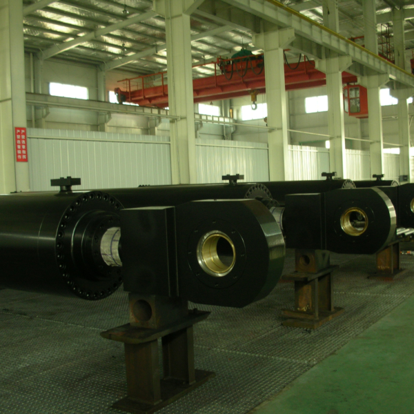
A pivot mount allows a cylinder to follow a moving linkage, but only if the pin axes and clearances allow the intended rotation. Misaligned pins can force the rod to bend as the cylinder moves. The first symptom may be gland wear, not an obviously damaged mount.
Two pins define a moving plane
A clevis-mounted cylinder can swing only around its pin axes. If the two axes are not parallel, the linkage asks the cylinder to twist or bend while it extends. The mechanism may still move when unloaded, because clearances and flexible hoses conceal the problem. Under load the brackets deflect, contact concentrates at one edge of a bushing, and the rod gland begins to wear. Trunnion bearings have a related requirement: the blocks must be aligned and supported so the trunnion is not used as a bending beam.
Parker’s cylinder safety guidance calls for parallel pin axes on clevis-mounted cylinders and aligned bearing blocks on trunnion mounts. During installation, cycle the mechanism at low load and verify free swing without interference at both ends. Check pin retention, bushing material, lubrication access and the bearing pressure under the maximum load. Do not assume a freely moving empty linkage will remain aligned under structural deflection at full load.
Inspect the machine before blaming the actuator
Remove load according to the machine procedure and compare bracket spacing and pin-axis direction with the approved drawing. Look for polished arcs, fretting, one-sided bushing wear and bent retainers. Measure pin and bore wear at multiple clock positions. Lubrication should reach the loaded surface; a grease fitting that is present but blocked does not meet that need. During a slow functional test, observe whether the body swings freely and whether the hoses constrain it near either endpoint.
A crane-linkage example
A luffing cylinder can swing freely with an empty boom while its mounting ears twist slightly under a lifted load. After months of duty, one edge of the rod bushing and one clevis bearing may be polished or worn. That pattern is a clue to the loaded geometry. When measuring, support the boom, check the pins against the bracket bores and compare the two pivot axes. Replacing only the cylinder seals would leave the side force. A repair may require bracket correction, bushing replacement or a revised joint, with the machine engineer approving the final alignment.
A useful acceptance check
After installation, record clearance and alignment at retracted, mid-stroke and extended positions. Then repeat at representative load if the machine design permits. Check whether a pin can be removed without forcing the brackets together after the load is safely supported; binding is a reason to investigate, not to hammer the pin through. Pin diameter alone is not a complete specification: bearing length, material, lubrication, retention and corrosion exposure all affect service life.
Checks to put on the drawing or test plan
- Measure parallelism and bracket spacing before inserting the pins.
- Inspect bearing contact and lubrication after an initial loaded cycle.
- Check cylinder swing and hose clearance across the complete mechanism travel.
Failure mode to avoid: Forcing a pin through offset brackets may make assembly possible while creating continuous side load in the cylinder.
Information to request before approval
- Pivot coordinates and bracket drawings.
- Pin diameters, materials and bushing details.
- Load cases and service environment.
For a related explanation, see cylinder side-load guide.
Referencias técnicas: Parker Cylinder Safety Guide. The cited manuals and product data describe their makers’ equipment; this article is independent engineering guidance and does not assign their ratings to Yongjian products.