


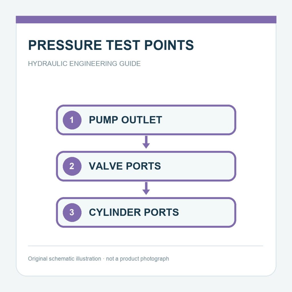
A single gauge at the hydraulic power unit cannot show what pressure reaches a distant actuator. Test points at selected positions make it possible to separate pump output, line loss, valve behavior and load-induced pressure during an operating cycle.
Measure across the suspected loss or control function
Useful locations may include pump outlet, both sides of a filter, pressure and work ports of a control valve and the cylinder ports. The actual choice depends on the schematic. Parker describes dedicated test-point fittings for high, low and vacuum measurements and for sampling. Connections must be rated for the pressure and fluid at their location and accessible without exposing personnel to moving equipment.
Engineering checks
- Identify normal and maximum pressure at each planned point.
- Put paired points around components whose pressure loss will be trended.
- Allow safe gauge connection and clear labeling.
- Use suitable transducer response when short pressure peaks matter.
- Document measurement conditions with load and oil temperature.
Common mistake to avoid
A low reading at the pump outlet and a low reading at the cylinder port have different causes. Without the location and timing of the measurement, “low pressure” is not a diagnosis.
Data to send with an inquiry
- Hydraulic schematic with proposed measurement positions.
- Expected pressure range and transient response.
- Connection standard, isolation and access requirements.
- Data-logging needs for commissioning or service.
Include the test-point map in the machine documentation so later readings can be compared at the same points and duty. For related selection guidance, see our cylinder port and pressure-drop guide.
Technical references: Parker SensoControl test-point data; Parker pressure monitoring case. Cover: original conceptual schematic, not a product photograph.