


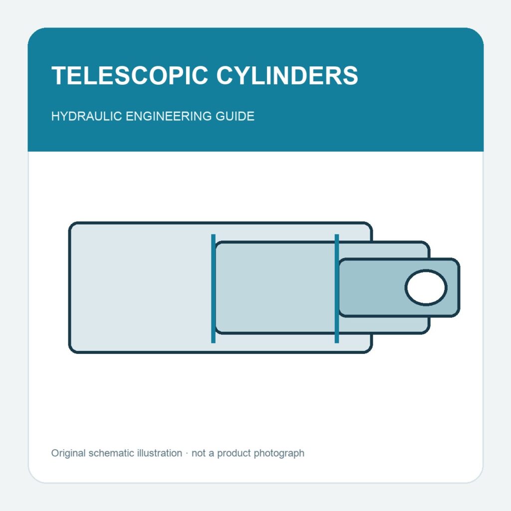
A telescopic hydraulic cylinder provides a long working stroke while fitting into a shorter retracted envelope. It uses nested moving stages of decreasing diameter rather than one long exposed rod. This is attractive for lifting and tilting equipment, but the change in stage area means its force and speed cannot be treated like those of a conventional single-stage cylinder.
How the stages move
In a common design, the largest moving stage extends first, followed by progressively smaller stages; retraction usually occurs in reverse order. Parker’s mobile-cylinder guide describes this sequence and distinguishes the main barrel from the moving stages and smallest plunger. The actual sequence and pressure behavior must still be checked against the selected model, especially for custom circuits.
Why force and speed change through the stroke
At a given pressure, ideal thrust follows the active stage’s effective area. As smaller stages begin to work, their available extension force is generally lower. At constant supplied flow, stage speed also changes because each stage displaces a different oil volume per unit of travel. The smallest working stage often sets the limiting lift capacity. A single catalog “maximum force” figure is therefore insufficient when a load changes with angle or position.
Single acting or double acting?
A single-acting telescopic cylinder extends under hydraulic pressure and needs gravity or another external force for return. A double-acting design uses hydraulic power in both directions. A horizontal application normally cannot rely on gravity for retraction, while a tipping body may do so if the geometry and load are suitable. Never assume that a single-acting lift will descend predictably under every loading condition; the valve and structural system must control the load.
Drawing and RFQ checks
- State closed length, extended length, total stroke and available mounting envelope.
- Provide load versus position, machine geometry and minimum force required in each stage.
- Define extension and retraction times, working pressure and expected flow.
- Check overlap, support, side loading, pins, return method and end-of-stroke control.
- Specify contamination, corrosion and service-access conditions.
For the underlying force calculation, see our cylinder force guide. A telescopic arrangement needs its own stage-by-stage assessment and a machine-level stability review before purchase.
References: Parker Mobile Cylinder Products and Application Guide; Parker Designing With Telescopic Cylinders. Cover: original conceptual schematic.