


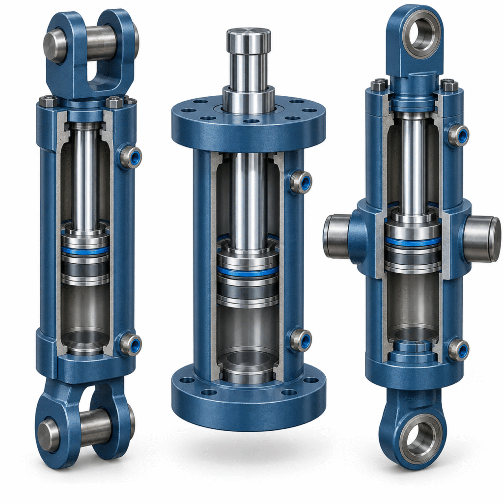
A cylinder mounting is part of the load path, not a minor catalog option. The barrel, rod connection, pins or bolts and supporting frame must transfer force while allowing the motion the machine actually makes. A correct bore and pressure rating cannot compensate for a mount that forces the rod sideways. This guide compares common mounting families and the information an engineer should put on a drawing.
First decide whether the load travels straight or follows an arc
A fixed, centerline mount suits a load that is externally guided in a straight line. A pivot mount allows the cylinder body to rotate as a boom, gate or linkage travels through an arc. This distinction should be decided from the machine kinematics before selecting a familiar-looking end fitting. A cylinder produces linear force; it is not a substitute for the machine’s guide bearings.
How the main mounting styles differ
| Mounting family | Typical use | Design check |
|---|---|---|
| Clevis or eye | Single-plane pivoting linkages | Pin shear, bearing pressure, articulation and alignment through the full stroke |
| Trunnion | Pivoting cylinder with a defined body pivot location | Trunnion support and pin loads; avoid unintended bending in the pins |
| Cap or head flange | Guided straight-line thrust or pull | Choose the flange end for the main force direction and verify frame stiffness |
| Foot or side lug | Space-constrained fixed installations | Eccentric loading, fastener design and positive location where needed |
These are families, not interchangeable dimensions. A clevis that fits the pin diameter may still have the wrong closed length or swing clearance. A foot mount can impose a turning moment on its bolts because its reaction is offset from the cylinder centerline. Parker’s mounting guidance makes the same distinction between centerline, foot and pivot configurations.
Check alignment at both ends of the stroke
Draw the rod-end and cap-end pivot centers in the fully retracted, intermediate and fully extended positions. Confirm that the proposed joint can articulate through the complete path without binding. For a one-plane linkage, a fixed clevis may work. If the machine moves out of plane, the joint arrangement needs a separate review; adding a spherical bearing does not automatically make an otherwise unsuitable cylinder safe. Also check the extended rod for compression buckling and the machine structure for deflection under peak load.
What to send with an RFQ
- General arrangement drawing with pivot centers, available envelope and required stroke.
- Maximum push and pull forces, working pressure, shock loads and duty cycle.
- Rod-end and base-end joint details, pin material and allowable articulation.
- Operating environment, corrosion protection and inspection requirements.
For a marine linkage, compare the installation needs with our marine deck crane cylinder. For a long guided press stroke, see the custom hydraulic press cylinder. Final mount dimensions and ratings must be checked against the actual machine drawing.
Technical reference: Parker hydraulic cylinder mounting guidance. The cover is a concept illustration, not a dimensioned product drawing.